– SAVE THE PACKING MATERIAL for return shipping or carrier inspection
and notify Gordon Instruments of any damage. An accessories bag is
enclosed with each preamp.
Rack kits (included: a pair of rack
ears and four mounting screws) are attached to the sides of the preamp and gain control
for rack
mounting.
CAUTION – The preamp may
be damaged by using screws longer than the 3/8" screws supplied
with the rack kits and outriggers.
Outriggers (a pair and four
mounting screws) are attached to both ends of the preamp’s right side
panel for freestanding applications. The rack ears can self-store by
mounting on both ends of the left side panel.
Placement – For best
results, the preamp should be located as close to the microphone or
instrument as possible, avoiding high vibration or sound pressure
levels, with a gain control at the monitor location. Audio cable length
and connections should be kept to a minimum, particularly between the
microphone or instrument and preamp input.
Preamp installation – The
preamp runs warm and, like any electronic gear, has better reliability
when kept cool; however, there are no special cooling requirements. In a
rack or case, when possible, maintain a 1U rack space above or below for
cooling and avoid installing the preamp next to warmer equipment.
The left (audio) half of the preamp should be located
away from any magnetic interference sources. The power supply magnetic
components have magnetic shields (to contain magnetic interference);
however, the audio circuitry does not. Magnetic materials (including
shielding) in or near the audio signal path are also a source of
magnetic interference and have been omitted in the preamp. Indications
of magnetic interference are distortion (less clarity) and noise (hum).
Cooling and magnetic interference are not a
consideration with freestanding applications.
Gain control installation
– The gain control does not handle audio signal and has no
installation restrictions.
Front panel
INPUT ¼" jack is
connected in parallel with the main INPUT XLR on the rear panel and the
input stage. The balanced ¼" input accepts balanced and unbalanced
sources. Unbalanced sources should be connected across the tip and
sleeve, with the ring shorted to the sleeve, or use a tip/sleeve plug.
Also see Signal path configurations. Pinout:
Sleeve – Screen/common/case and negative phantom
supply
Tip – Positive signal and positive phantom supply
Ring – Negative signal and positive phantom supply
CAUTION – Mute before
changing input connections.
STATUS lamp indicates normal
operation of the preamplifier and gain control. The STATUS lamp is off
when the ac supply is interrupted and flashes under the following
conditions:
• Ac supply turn-on/low-line enables the mute
function for thirty seconds at turn-on and for the duration of ac
low-line.
• Phantom supply turn on/off enables the mute
function and lasts for thirty seconds.
• Gain control fault enables the mute
function and can be caused by an ac-coupled, shorted, broken, or
disconnected control run.
• Output overload enables electronic
protection to limit the output signal.
• Standby is enabled by a lengthy mute and is
indicated by a shorter flash than the other conditions.
A flashing STATUS lamp in the absence of the above
causes may indicate an internal fault – contact Gordon Instruments.
+48V switch controls the
phantom supply with a soft turn-on/off, applying +48 volt dc to the
input via 6.81k ohm resistors. Audio out is muted briefly when the
phantom supply is turned on or off.
CAUTION – Do not change
input connections while the phantom supply is on.
Gain control sets the gain
for each channel in 2.5dB steps from 12.5 to 70dB.
True gain control – The
gain control sets the amount of open-loop gain in the signal path. This
contributes to operational advantages, including:
• No gain staging – The signal path is
automatically configured across the gain range for the least signal
processing at minimum distortion and maximum dynamic range.
• No attenuators, including input pads – The input
clips after the output, across the gain range, and the output clips
above +30dBm.
• No sweet spot – In addition to dynamic range,
bandwidth is maintained across the gain range. Noise is less at lower
gain settings, and roll-off and balance shifts are minimized over the
gain range.
+24dBu peak indicator
monitors pin 2 of the main OUTPUT XLR and flashes a minimum of 100
milliseconds (for transients) up to a continuous one-second blink to
indicate level is within 6dB of maximum output.
MUTE switch, when depressed,
overrides the adjacent gain control to provide a full audio mute on each
channel.
Standby is enabled after a
channel has been muted continuously for 10 hours, reducing bias,
phantom, and power consumption for that channel. Unmute to disable
standby. An internal jumper can disable standby or extend the mute
interval from 10 to 20 hours.
INVERT switch inverts the
main input signal at the output by reversing the signals to the XLR pins
2 and 3.
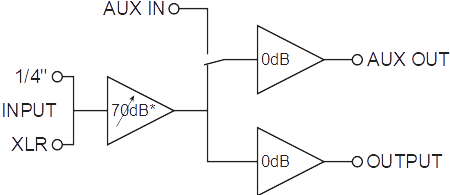
AUX IN switch selects
between the main input and the AUX input for the main output's source,
or for the AUX output's source, when equipped with the Aux output
option. Also see AUX input/output options.
REMOTE switch selects
between the inboard controls and an outboard gain control for remote
control via an XLR cable plugged into the GAIN CONTROL connector on the
rear panel.
Rear panel
IEC-320 power connector/fuse holder
– Connect the supplied power cord here and to a grounded ac line with
voltage as marked on the rear panel (100V, 115V, or 230V). After the
turn-on sequence (about thirty seconds), twenty minutes of warm up is
recommended. Production burn-in (150 hours with signal applied) was
performed before final testing and the preamp will continue to
"season" with use.
WARNING – Do not break the
safety ground connection through the power cord.
Fuse:
• For 100V – T600mA, time-lag, 5x20mm (two
required, included)
• For 115V – 500mA, time-delay, 1/4x1-1/4in
(included)
• For 230V – T250mA, time-lag, 5x20mm (two
required, included)
WARNING – Replacement
fuses (not included) must be the same type and rating.